|
The value of Kv can be calculated according to the values given,
such as: flow, Pressure drop and data of the operating conditions
of the installation.
| Liquids (water, etc.) |
P2>PS |
 |
- Q = Flow rate (m3/h)
- DP = Pressure drop (bar)
- r = Density (kg/dm3)
|
| Saturated steam |
P2>P2/2 |
 |
- G = Mass flow rate (kg/h)
- DP = Pressure drop (bar)
- P2 = Pressure downstream of the valve (absolute bar)
- P1= Pressure upstream of the valve (absolute bar)
|
| P2<P1/2 |
 |
| Superheated steam |
P2>P2/2 |
 |
- G = Mass flow rate (kg/h)
- DP =Pressure drop (bar)
- P1= Pressure upstream of the valve (absolute bar)
- P2 = Pressure downstream of the valve (absolute bar)
- v2 = Specific volume (m3/kg), under P2 and T1
- v = Specific volume (m3/kg), under P1/2 et T1
- T1 = Température en amont (K)
|
| P2<P1/2 |
 |
| Gas |
P2>P2/2 |
 |
- Qn = Mass flow rate at 0°C and 1013 mbar (kg/h)
- rn = Density of gas at 0°C and 1013 mbar (kg/Nm3)
- DP =Pressure drop (bar)
- P2 = Pressure downstream of the valve (absolute bar)
- P1= Pressure upstream of the valve (absolute bar)
- T1 = Upstream temperature (K)
|
| P2<P1/2 |
 |
Le Kvs of the valve:
To characterize the standard valves, one gives a Kvs coefficient,
which corresponds at the coefficient Kv for a nominal displacement
of H 100 of the valve
For each type of standard valve, one gives a nominal displacement
of H100 for which the valve can be regarded as completion open.
Le Kvo of the valve:
It is the leakage rate which crosses the valve if it presents
a pressure loss of 1 bar (DPv =1 bar) when it is completely closed.
Kvo is expressed in m³/h.
Leakage rate
The leakage rate of a valve is the ratio Kvo / Kvs
For a new valve, this leakage rate must be lower than 0.05
%.
| Coefficient of flow Kv for a valve |
It is the flow of water Q in m3/h measured at 4°C (Density
= 1000kg/m3) which for a pressure loss of 1 bar, passes through
the valve considered as entirely open.
A valve under dimensioned can generate a fall of pressure raised
through of the device and can consequently damage the seat of the
valve by erosion.
Conversely a oversize control valve can involve an unstable operation
of the installation.
For each type of valve, the manufacturer indicates a limit differential
pressure acceptable which depends on its diameter, of the method
of construction, the power of the servo-motor, the temperature of
the fluid, the leakage rate and of the maximum flow which crosses
it.

With:
- Q = Actual flow rate in m3/h at the temperature
x
- r = Density of the water in kg/dm3 (depends on
the temperature)
- DP = Pressure drop through the valve in bar
It is the difference in pressure between the inlet and the outlet
of the valve. It is thus its pressure loss.
The value of Kv in the same way is used to calculate the pressure
drop in a valve according to the flow which crosses it.

With:
- Q = Actual water Flow in m3/h at temperature x
- r = Density of the water in kg/dm3 (depends on
the temperature)
- DP = Pressure drop through the valve in bar
The principal function of a control valve is to ensure the progressiveness
of a flow. It is the authority of the valve which will determine
the stability of the control system.
This progressiveness will be quantified by the authority of the
valve.

- DPv = Pressure loss of the entirely open valve for the
nominal capacity l
- DPL = Pressure loss of the variable flow circuit.
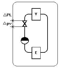 |
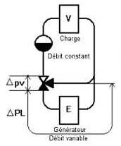 |
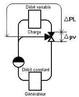 |
|
Changeable flow rates
|
Mix flow rate
|
Circuit de répartition
|
- E = Generator of heat
- V = Emetteur de chaleur - Transmitting of heat
| Characteristics of the valves |
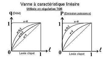
| Valve at linear characteristic |
|
|
|
The best progressiveness of the thermal power is obtained
when the valve has an authority, has = 1. It is unthinkable
to choose this value; therefore progressiveness will be poor
with this type of valve.
To use this type of valve in cpntrol system, it would be
necessary to regulate the proportional tape to a very high
value. This valve cannot be used in progressive control.
|
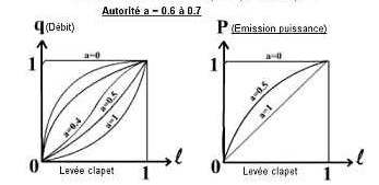
| Valve with square-law characteristic - Vanne
à caractéristique quadratique |
|
|
|
Best progressiveness would be obtained for an authority,
a = 1. But however for A = 0.5, the authority of the valve
not being linear can in spite of very given satisfaction.
If the total head of the pump allows it, there would be
interest to give an authority for example from 0.6 to
0.7
|
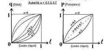
| Valve with characteristic logarithmic curve |
|
|
|
In this type of valve, the displacement of the valve produces
a variation of flow proportional to the preceding total
flow the change. The best progressiveness of power is
obtained for 0.6 to 0.7.
|
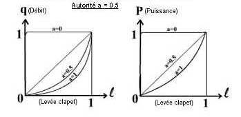
| Valve at linear calorific power |
|
|
|
In this type of valve the manufacturer designed the valve
in order to obtain a calorific power proportional to the
lifting of the valve, for an authority has = 0.5. A too
large authority would have the same harmful effect as
a too small authority.
|
Last update:
|


