| Characteristics and functions of the program |
This calculation program on Excel makes it possible to dimension
and carry out the calculation of the pressure losses on the
ductworks and air distribution systems.
AeroDuct can be distributed with calculation
in English system (e.g., ounces, pounds, inches, and feet) and
common units in the metric system (e.g., grams, kilograms, meters,
and centimeters). .
It applies in all types of duct and holds account particularly
on the operating conditions and specific Characteristics on
the ductworks, such as:
- The temperature of the air conveyed
- The level of altitude or is located the installation
- The nature of the various types of materials used (steel ductwork, copper,
PVC, built walls, etc)
- The geometrical shapes of ductworks (circular, quadrangular, oblong)
- The various types of pressure loss coefficients
- Le contrôle des vitesses silencieuses de passage d'air.
- The control of air speeds.
Complementary modules of calculations are incorporated in the program, such
as:
- K-factor editor of the local pressure loss
- Equivalent K-factor calculator.
- Calculator for evaluation of the motorized power of the ventilator, according
to the calculated load.
The calculation program is equipped with a customized command bar giving access
to the various procedures, boxes of calculation and macro commands.
The working files are created separately making it possible to reduce the data
storage.
| Display of the table of calculation of pressure loss |
The working file can be made up of various computation sheets. You can from
the same file, to insert a new computation sheet or to duplicate the computation
sheet in progress for the study of a similar ductwork and to make the complementary
modifications thereafter.
If you forget some elements from the ductwork, you can add lines of calculation
anywhere, without deteriorating the phases of calculations.
You can also choose the unit of pressure of your choice in the study:
- Pa (Pascal)
- Pounds per square foot (lbf/sq ft) = 47.88026 Pa
- Torr / mm Hg (133.3226 Pa)
- Inches w.g (248.6 Pa)
- kPa ( = 1000 Pa)
- Psi (Pound per square inch (lbf/sq. in) = 6894.757 Pa)
AeroDuct can be distributed with calculation in Metric
system or English unit.
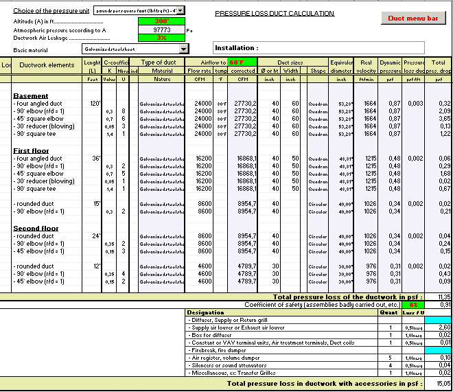
For each sheet of the table of calculation, the presentation is done, such
as:
In basic display:

The hygienic airflow or smoke extract systems are indicated generally in the
standards on a air mass of reference of 0.0746 lb/ft^3 (1,200 kg/m3) - (equivalent
to: 68°F (20°C) - 40%)
The basic airflow is corrected automatically in function:
- Of the altitude of the site.
- Of the leakage rate of air estimated in the ductworks.
- Of the temperature of airflow in the ductwork compared to the basic temperature
taken into account in the calculation of the installation or the airflow of
reference.
The real speed of the airflow in the ductwork is carried out from the corrected
airflow.
A displaying in yellow of the cell concerned indicates speeds of air higher
than the quiet values recommended in the installations at low pressure.
It is highly advised to envisage a coefficient of safety margin:
- The assemblies are often badly carried out, blocking partially the passage
of the fluid.
- An estimated dusty ductwork can be considered.
- With the ageing of the ductwork, a possible corrosion can increase the pressure
losses by friction.
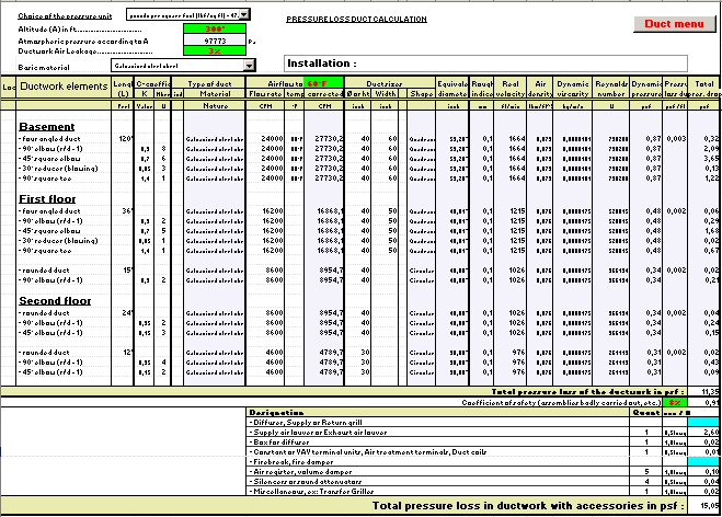
In total displaying, the table visualizes in complement:
- Indices of surface roughness.
- The air density.
- The dynamic viscosity of the air.
- The Reynolds number.

All the colour cells of calculation are programmed.
Air speeds recommended
Installations "low pressure" (maximum Speed 1550 to 2000 Ft/min
- 8 to 10 m/s)
| Airflow in ducts |
Maximum velocity |
| - Maxi flow rate < 175 CFM (300 m³/h) |
490 ft/min ( 2.5 m/s) |
| - Maxi flow rate < 590 CFM (1000 m³/h) |
590 ft/min ( 3 m/s) |
| - Maxi flow rate < 1200 CFM (2000 m³/h) |
785 ft/min ( 4 m/s) |
| - Maxi flow rate < 2350 CFM (4000 m³/h) |
980 ft/min ( 5 m/s) |
| - Maxi flow rate < 5900 CFM (10000 m³/h) |
1180 ft/min ( 6 m/s) |
| - Maxi flow rate > 5900 CFM (10000 m³/h) |
1380 ft/min ( 7 m/s) |
Installations "high pressure" (speeds of air > to 2000 ft/min
- 10 m/s) - Ejector-convectors, Variable Air Volume Systems (VAV) or variable
Induction units, etc.
| Airflow in ducts |
Shaft |
Corridors |
Premises |
| - 59000 to 41000 CFM - (100000 to 70000 m3/h) |
5800 ft/min (30 m/s) |
|
|
| - 41000 to 23500 CFM - (70000 to 40000 m3/h) |
4900 ft/min (25 m/s) |
|
|
| - 23500 to 14700 CFM - (40000 à 25000 m3/h) |
4300 ft/min (22 m/s) |
3940 ft/min (20 m/s) |
|
| - 14700 to 10000 CFM - (25000 à 17000 m3/h) |
3940 ft/min (20 m/s) |
3350 ft/min (17 m/s) |
3150 ft/min (16 m/s) |
| - 10000 to 5900 CFM - (17000 à 10000 m3/h) |
3350 ft/min (17 m/s) |
2950 ft/min (15 m/s) |
2750 ft/min (14 m/s) |
| - 5900 to 2950 CFM - (10000 à 5000 m3/h) |
2950 ft/min (15 m/s) |
2350 ft/min (12 m/s) |
2350 ft/min (12 m/s) |
| - 2950 to 1200 CFM - (5000 à 2000 m3/h) |
2350 ft/min (12 m/s) |
2000 ft/min (10 m/s) |
2000 ft/min (10 m/s) |
| - Inferior to 1200 CFM (2000 m3/h) |
2000 ft/min (10 m/s) |
2000 ft/min (10 m/s) |
2000 ft/min (10 m/s) |
| - Fire dampers |
2000 ft/min (10 m/s) |
2000 ft/min (10 m/s) |
2000 ft/min (10 m/s) |
- It is recommended to leave in the main ducts at a speed of 3940 to 4300
ft/min (20 to 22m/s).
- The main and secondary ducts are generally calculated on a basis of 0.0034
In.wg (0.85 Pa).
- The boxes are selected on the basis of acceptable noise level when the pressure
at the entry of the boxes is of 3 In.wg (750 Pa).
- The reduction speed can cause a renewal speed.
Dual-Duct VAV Systems (average or high pressure)
- The circuit of the cold air ducts is calculated for 100% of the necessary
flow.
- On the other hand, for the hot air ducts, one admits 50% to 75% of the
cold air flow according to thermal loads.
- The variation between the temperature of the buildings in summer and the
air in the cold air duct is 50 to 55.5 °F (10 to 13°C).
- In summer, the temperature of the hot air in the duct is maintained at
least with +5.4°F (+ 3°C) above the average temperature of the air
outlet.
The air velocity in the ducts cannot exceed a certain value. It results a minimal
section of ducts below from which it is misadvised going down for following
reasons:
- Increase the noise of rustle of the air in the strait ducts and especially
on the level of the deviations.
- Increase the pressure losses and the energy consumed by the ventilator.
Example: a reduction in half of the section doubles the air velocity increases
the pressure losses and the absorptive power by the ventilator by a factor 4.
Last update:
|

